
Super Retrowidepie! 3.5" Raspberry pi 2+ Portable Gaming Machine
Description
This is a wide version of the Super Retropiepod https://www.thingiverse.com/thing:3293876 Setup like a Gameboy Advance with the same 3.5" screen and most parts as the Super Retropiepod. #Features: - 3.5" TFT LCD Backlit color screen - Stereo Speakers - Larger Battery compared to Super Retropiepod - Easy to print and assemble - Uses common easily available parts - Micro USB charging - Ethernet and USB ports accessible - SD card accessible - Stronger than Super Retropiepod # Print the Templates Print Button Board template.STL and D-pad Template.STL these are cut and drill guides for the button boards. Drill the 4 holes for the mounting then using the other holes mark the button positions close as possible. #Modify the screen  Here's the stock wiring. You can remove all of it to get started. The points we need are marked. The 5v + needs to go on the second pin from the left on the top of the small chip in the bottom right of the board.  Here's the screen all wired for 5v and video. You only need the 3 wires. I plan on running these to the GPIO on the Pi but the video wire needs to be soldered to pad PP24 on the back of the pi.  Here's the composite video out pad on my test pi for example. #Setup Retropie Using something like Win32 Disk Imager on windows you can easily setup Retropie. - Download Retropie for your pi https://retropie.org.uk/download/ - Win32 Disk Imager download https://sourceforge.net/projects/win32diskimager/files/latest/download Burn the files to your SD card and edit the config.txt adding the following lines to the end of the file: sdtv_mode=0 hdmi_ignore_edid_audio=1 framebuffer_width=480 framebuffer_height=320 avoid_warnings=1 This sets the output and screen resolution as well as turning off low voltage warnings [Since the powerboost will cause them sometimes but it hurts nothing.] #Setup Controls The controls are based off the Adafruit sccript here: https://github.com/adafruit/Adafruit-Retrogame I have included a custom config file. The easiest way to get this working is use SSH and the above script to install the PiGRRL 2 controls. Once done shutdown the machine and remove the SD card then copy my custom config to it overwriting the current retrogame.cfg in the /boot/ partition. Now you can setup the keys in RetroPie. The config file also shows what pins to hook the buttons too. These buttons work by grounding the pin to send the signal and the Raspberry Pi has internal pull-ups so no additional components are needed. The pin numbers are the GPIO or BCM numbers. 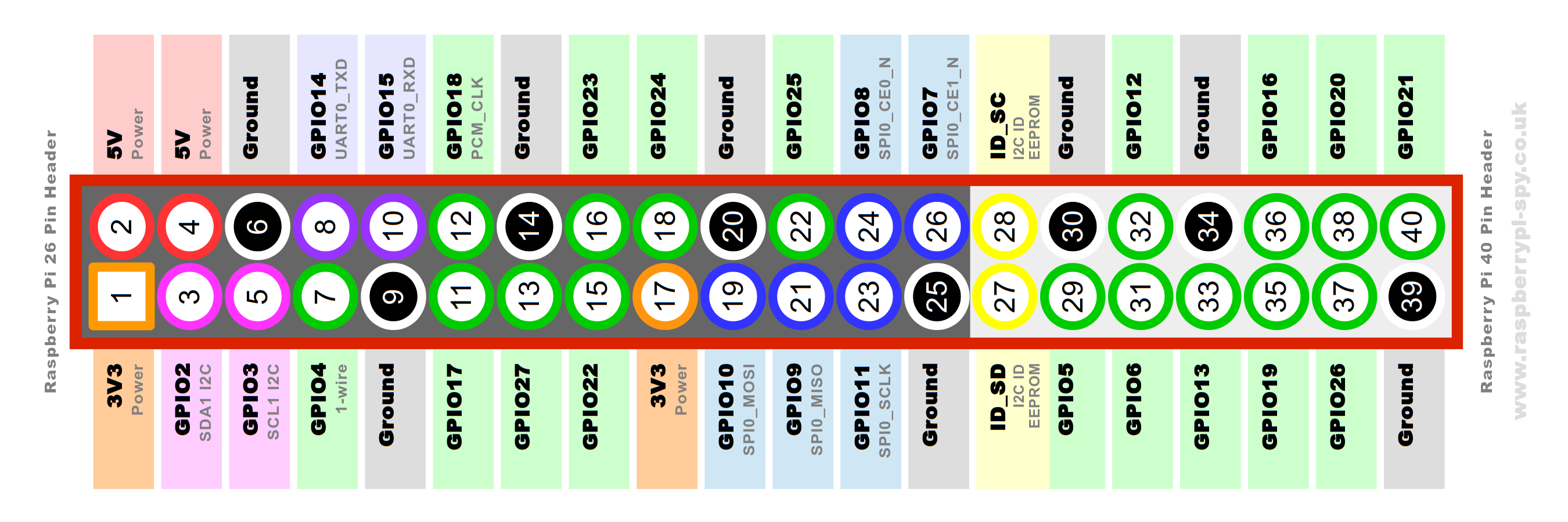 The switch is wired so it goes from Off to On with no sounds to On with sounds.  There's a 3mm hole and space for LED to indicate low battery. This is attached to +5v with a resistor and grounded to the LBO pin on the Powerboost1000c. #Use Themes to make it easier to see! If you plug into an HDMI TV it will switch to that on boot automatically. Connect it to the internet and go to Retropie - Themes. Scroll down and find "TFT". This is a theme meant for these small, low res screens that makes it much easier to use! #BOM: - Powerboost 1000c https://www.adafruit.com/product/2465 or https://www.amazon.com/Adafruit-PowerBoost-1000-Charger-Rechargeable/dp/B01BMRBTH2 - 3.5" LCD https://www.amazon.com/gp/product/B0045IIZKU - 3 Position switch https://www.amazon.com/gp/product/B008DFYHV2 - Tactile Buttons https://www.amazon.com/CO-RODE-Tact-Button-Switch-6x6x5mm/dp/B00W0YUV1W - Right angle tactiole buttons https://www.amazon.com/gp/product/B00E0KZS76 - 2 x 18650's These are 3400mah each https://www.amazon.com/gp/product/B01C4GFVN8 - Stereo Amp https://www.amazon.com/NOYITO-TDA2822-Channel-Stereo-Amplifier/dp/B07HRDC2RM - 24x15x4mm speakers https://www.amazon.com/Aexit-Speaker-Magnetic-Trumpet-Accessories/dp/B07B2DNSYX - 2x M3x30mm taper head screws for the shoulder buttons. #Thank you Watch and like, updates will be incoming! #Do not print this yet! #Updates! - 12/25/18 First update, added buttons and mounting bosses. Worked out where everything has to go and how the shoulder buttons will work. They swing on pivots between the case halves. Moved the split far to the rear of the case for easier mounting. - 12/26/18 Added dual shoulder buttons and finalized how the case fits together. Used larger mounting bosses for increased strength. All files updated. - 12/27/18 Printed test prints and updated files. Fixed alignment of SD card slot and made all mounting holes ready. Many slight changes. All files updated! - 12/27/18 Update 2! Updated all files. I forgot to add the cutout and mount for the power switch. Added to back cover. Also added branding to back cover. All parts can be printed without support. - 12/28/18 Added air vents and made final tweaks. Printing and Assembling unit now. All files updated. - 12/29/18 #All ready to go! All files updated and confirmed, Retropie config added. Instructions added. - 1/6/19 New year, new plan for the shoulder buttons. I made some channels that hold a 14mm wide board for the switches. This is for 6x6x5mm tactile like the others. This should make the shoulder buttons easier however it fouls the other boards slightly. Solution? Cut out some of the other board! Tolerances... All files updated and I will be doing more test prints. - 1/7/19 Went through and made new printable templates for the boards. These have a 4.5mm hole in 7 mm thick to hold a standard sharpie in perfect center over each hole. The outside can be traced to make that cut. Shoulder buttons and D=pad updated too. The D-pad spire now glues to the board between the switches, I used superglue. - 1/10/19 Assembly continues. Uploaded newest files and a few new pictures. Black one is the newest print and now everything fits and works properly. The shoulder buttons are not the most graceful solution but they work great once assembled. The templates for the boards are meant to be used with the hollow side against the PCB. The holes are sized to center a standard Sharpie marker to mark drill holes, outline and switch positions. I will also make Eagle files for custom PCBs to fit. - 1/12/19 Uploaded all new files. Changed the design for the should buttons, again. Easier now but the PCB dimensions are important. - 1/17/19 PCBs are being made now. Those will be uploaded as gerber files for you to have made later. All STLs updated.
Statistics
Likes
26
Downloads
0